I grew up playing ping pong, so I wanted a way to practice consistently without relying on someone else at all times. So I figured the easiest way to do that is to just design a robot that does this.
I started by figuring out the launch mechanism, and I considered using a linear actuator, or even a numatic system, but I settled on a dual-wheel system driven by two brushed DC motors. This way, I can very easily control the speed of the ball, and in the future when I want to incorporate spin, I can vary the speed of one wheel and that would put a spin on the ball.
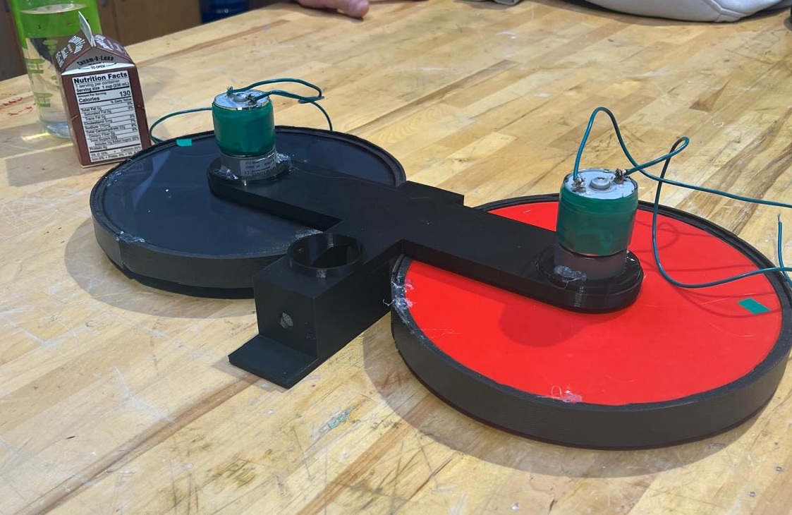
I started prototyping using different sized wheels to achieve different velocities. However, the bigger the wheel, the more moment of inertia it had, and therefore the more torque it needed from the motor. I quickly realized that I must optimize my wheel geometry to create a balance of high tangential velocity and low moment of inertia. Through these early prototypes, I also realized the need for a proper grippy material on the 3D printed wheels for efficient energy transfer.
At this stage, I also lacked a proper testing apparatus; the 3D printed one shown would flex under load, making it difficult to determine the optimal spacing between wheels for regulation ping pong balls. Nonetheless, I eventually got my first launch.
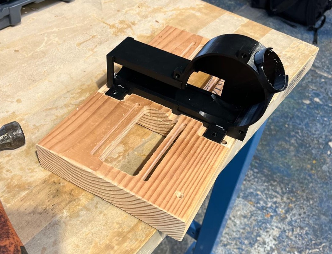
Still, the launch wasn't powerful enough to be competitive. I wanted to design a robot that challenges my ping pong skills, and not just barely make the ball over the net. Through multiple iterations, I optimized wheel geometry and selected more powerful motors capable of delivering the required speed and torque. I CNC-machined a rigid wooden test fixture to precisely mount the motors, eliminating flex and ensuring consistent alignment.
Using this fixture, I manually adjusted wheel spacing and experimentally identified the optimal distance for consistent launches. I also applied Silicone tape to the outside of the wheels to improve grip. With these improvements, the launching mechanism was close to being done.
From here, I added a mechanism to control the frequency of the shots. This involved using a servo with a 3D printed arm that goes up, grabs the ball, and then feeds it through the two wheels. I added an arduino and used an external power supply to power the arduino and the motors. I used a mosfet driver to control the motors with a PWM signal from the arduino. I added a potentiometer as an analog input to control the speed of the wheels, and a power switch for the circuit. The Frequency of the shots can also be controlled directly from the arduino code.
I then mounted the CNC machined apparatus to a tripod to easily control pitch and yaw when the launcher is put in front of a ping pong table.
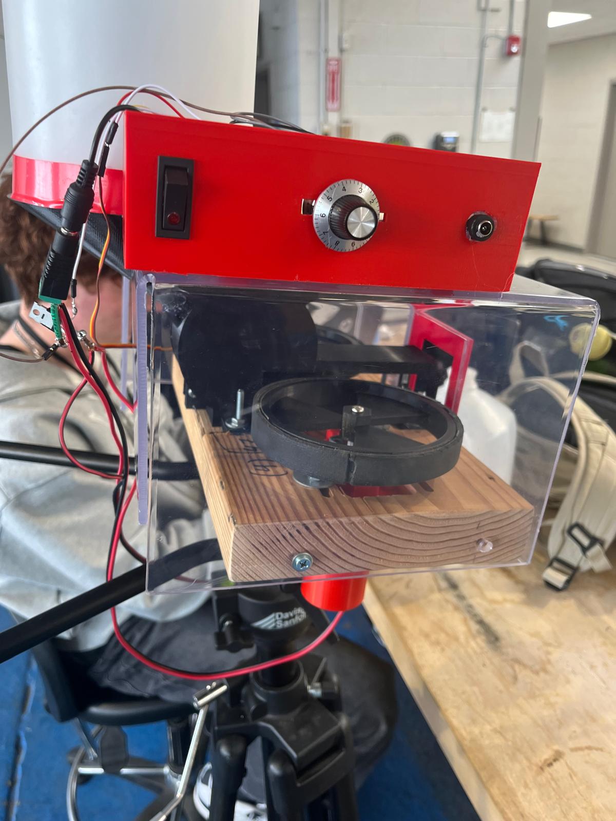
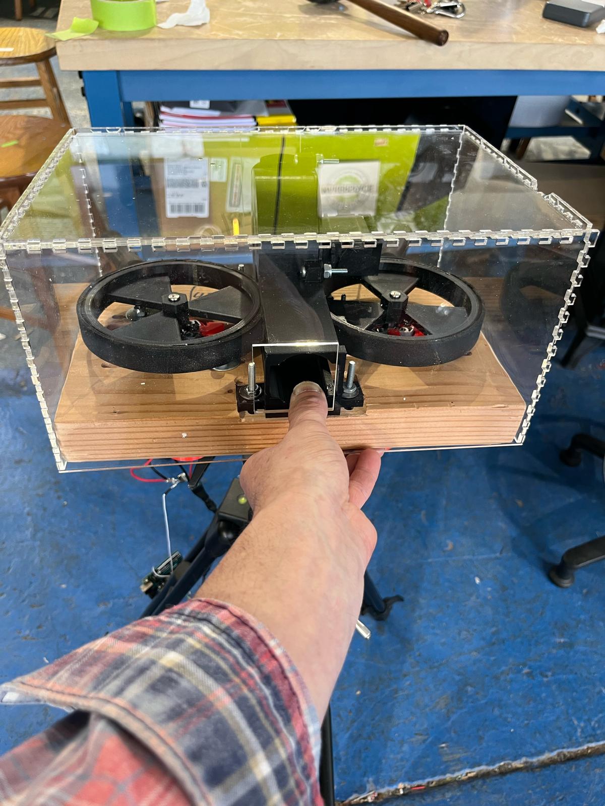
I made an enclosure out of acrylic for safety, and I housed all the electronics in a controls box that I mounted on top of the acrylic enclosure. All electronics were housed in a dedicated enclosure mounted on top of the launcher.
The completed launcher was presented in March 2024 at a New Jersey Teachers Conference at Montclair State University, where I talked about the importance of hands-on learning and its effects on students' motivation to contribute to their communities.